| 编辑推荐: |
本文通过示例介绍如何通过绘制 UML 来使用 JUDE,希望对您的学习有所帮助。
本文来自于change-vision.com,火龙果软件Alice编辑,推荐。 |
|
我希望通过使用 JUDE 学习和体验 UML 是可以用来绘制 UML 的建模工具。我会的 通过示例绘制 UML 来指导您如何使用 JUDE。
拿起鼠标并绘制 UML 并通读此内容。 我希望你喜欢和我一起体验 UML。
1-1. Overview
1-2. UML 和 UML 工具
绘制 UML 时,是手绘还是使用工具?体验使用工具的优势。为什么是工具?以下是众多优势中的一小部分:
- 允许您绘制干净的图表
- 它以适当的大小绘制元素
- 与其他人共享或交换 UML 模型很容易
- 您可以一遍又一遍地使用撤消/重做来尝试找出您真正想要的是什么
- 当您根据 UML 规范绘制图表时,它会给您一个警报
- 数据可以通过多种方式输入(图表、树状结构..等)
- 数据易于重用
- 您可以管理所有数据以及它们之间的引用
如果您是 UML 的初学者,您会发现 #4 和 #5 对您非常有帮助。因为错误很容易被 “撤销”,所以你可以制作完美的 UML 图。此外,当您从类中创建抽象类时,抽象类名将自动以斜体显示,就像它在规范中应该显示的方式一样。通过使用 JUDE 绘制 UML,您可以获得更多优势。JUDE 将成为您的 UML 导师。试着玩弄它。请记住,如果您犯了错误,您可以随时执行“撤消”作并重试。
1-3. JUDE 的描述
现在有许多 UML 工具可供您使用。我更喜欢的是 “JUDE/Community” (JUDE 代表 Java 和 UML 开发人员环境)。我有点偏见,我是 JUDE 开发团队的一员,多年来一直在开发和完善 JUDE。我希望更多的人尝试 JUDE 并像我一样学会热爱它。
JUDE 有两个版本;JUDE/Community(免费版)和 JUDE/Professional(产品版)。JUDE 具有以下特点:
- JUDE/Community 支持所有基本的 UML 1.4 图表
- JUDE/Professional 支持所有基本的 UML 1.4 图、一些 UML 2.0 规范和实体关系图(从 JUDE/Professional 版本 3.2 开始支持 ER 图)
- 无限的撤消/重做功能
- 使用“地图视图”自由拖动、滚动、更改视图,以便轻松编辑大尺寸图表
- 导入和导出 Java 源文件
- 自动生成包含模型信息的类图
有关 JUDE 功能的更多信息,请查看 JUDE/社区页面 。 1-4. JUDE 的安装
现在让我们安装 JUDE。您需要先安装 Java Environment 才能运行 JUDE,因此请安装 Java Environment。安装它们都非常容易。
1-4-1 系统需求
| 操作系统: |
Windows 2000, XP, Vista |
| CPU: |
Pentium III 600MHz 或更高 |
| 内存: |
256MB 或更高 |
Java 环境
(必需):
|
Sun Microsystems
J2SE 1.4.1_07 或更高版本,或者 J2SE 1.4.2_05 或更高版本,或者 JDK5.0
(从 JUDE/Community 3.1 开始支持 JDK 5.0) |
JUDE 适用于 Windows98、Linux 和 MacOS 等 J2SE 环境。但是,我们还没有对它们进行足够的测试,无法正式支持这些环境。所以我建议在 Windows 上安装 JUDE。如果您需要有关如何在除 Windows 以外的其他环境中进行设置的信息,请参阅此 常见问题解答
1-4-2 安装 Java 环境
如果您已经在计算机上安装了所需版本的 Java 环境,请跳过此步骤并转到下一步。如果您还没有,请转到 Sun Microsystems 页面并按照其页面上的步骤安装 Java Environment。在安装 Java 环境之前,请阅读以下注意事项。
- 请确保安装所需版本的 Java 环境。JUDE 可能无法在不受支持的 Java 版本上正常工作。
- 请确保在安装 J2SE 时包含 J2RE。(默认情况下,JUDE 将使用安装在作系统中的 J2RE)
1-4-3 下载 JUDE
接下来从 下载页面 下载 JUDE。
选择最新版本的 jude-community-x_x-setup.exe(约 5MB)并下载。(顺便说一句,我用了 JUDE/Community 3.2 来写这篇文章。
1-4-4 安装 JUDE
下载后,双击该文件开始安装 JUDE。双击它后,安装程序向导将启动,您所要做的就是指定安装位置。
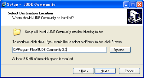
如果您使用的是 Windows98 或 ME,则必须使用编辑器打开名为 jude.bat 的文件,然后在 JUDE/HOME 变量中设置文件夹的绝对路径。jude.bat 文件位于 JUDE 安装文件夹中。
1-4-5 运行 JUDE
从 Windows 开始菜单启动 JUDE。当您启动 JUDE 时,将显示此图像。
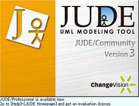
(The image of JUDE starting)
1-5. JUDE的基本组成和基本操作
现在,我将向您展示 JUDE 的屏幕内容,并指导您一些基本作。
1-5-1 基本组件
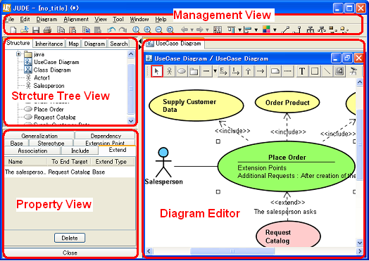
- 管理视图
管理视图具有主菜单,其中包括与整个项目相关的功能,例如文件作和编辑,以及用于常用功能的工具栏。
- 图表编辑器
图表编辑器用于编辑图表和模型。您可以同时打开多个图表。
- 结构树
它以树结构显示模型。您可以使用此处模型元素的 Pop-Up 菜单执行各种作。
- 继承树
继承树视图 根据类之间的继承关系以树结构显示模型。
- 映射视图
映射视图提供在 Diagram Editor 中打开的图表的概述。可以通过右键单击拖动来指定 Diagram Editor 中显示的区域,并且可以通过左键拖动来滚动 Diagram Editor 中的图表。此功能尤其适用于大型图表。
- Property View
属性视图用于显示和编辑模型元素的属性。
1-5-2 创建新项目
在 JUDE 中,UML 数据将另存为 (Name).jude。这些文件称为项目文件。首次启动 JUDE ata 时,没有打开任何项目。好了,现在让我们创建一个新项目。从主菜单中选择 [文件] - [新建]。创建新文件后,将显示 Structure Tree 和 Property View。
默认项目
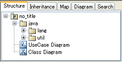
“UseCase diagram” 和 “Class diagram” 是在具有 “no_title” 的新项目中创建的。“no title” 包与 Java 默认包相关联。但是,在本教程中,我们不打算使用 Export Java 功能,因此让我们继续。Java 包与 Java 平台 API 相关联,它包含诸如 “String” 和 “Vector” 等基本类..等。这些类可以用作 Attributes 的类型。
1-5-3 创建包和图表
要创建新包,主要使用 Structure Tree 中的 Pop-Up 菜单。要创建新图表,请从结构树的弹出菜单中选择 [创建图表] 或从主菜单的 [图表] 中选择。
您可以使用 JUDE/Community(3.2) 创建的图表有:
- 类图
- 使用案例图
- 状态图
- 活动图
- 序列图
- 协作图
- 组件图
- 部署图
- 还支持对象、包、健壮性图。
1-5-4 How to create and edit items
用工具画图的基本作和一般的绘图工具几乎一样。如果您从未使用过绘图软件并且没有使用它们的经验,您将不得不习惯它,所以让我们开始吧。
1-6 关于保龄球的 UML
现在一切都设置好了,我们准备好绘制图表了。我们应该画什么图表?你最近去打保龄球了吗?我自己也很喜欢我们公司前几天举办的保龄球比赛。我猜大多数人都打过保龄球。因此,这次让我们使用 uml 的主题 bowling。让我们绘制系统的 UML 来显示保龄球分数。
保龄球比分
以下是请求。
- 比赛开始后显示保龄球比分的轨迹。
- 每次玩家投掷碗时更新分数。
- 玩家可以在游戏中更改分数。
- 在有人进行打击时显示动画。
我们在这里的目的是尝试使用 UML 建模工具体验 UML。绘制完美的图表并不重要。然后让我们开始吧。准备好了吗?
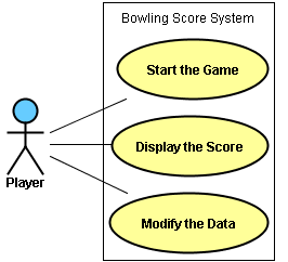
1-7 绘制用例图
现在让我们开始绘制图表,我们将从一个 UseCase 图开始。我们将绘制下图所示的图表。
使用案例图
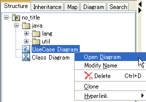
打开默认项目文件附带的 UseCase 图。右键单击结构视图中的 UseCase 图,然后在弹出菜单中选择 [打开图表] 或双击它以在图表编辑器中打开 UseCase 图。
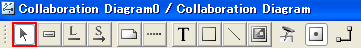
在 Diagram Editor 中,有一个工具调色板,其中包含用于编辑图表的按钮。

如果您想知道按钮的用途,请将鼠标指针放在按钮上,Tooltip 将显示按钮的描述。在图表编辑器上,您将使用这些按钮绘制切换模式的图表。例如,当您在图表编辑器上移动元素时,打开 [选择模式],然后选择要移动的元素,然后您可以移动它们。如果要连续创建某个元素,请将模式切换到 [锁定所选模式]...等。
| 按钮 |
描述 |
 |
选择 Mode(模式)。在此模式开启期间,您可以选择、编辑、移动和更改项目的大小。 |
 |
Lock Selected Mode(锁定选定模式)。它使您能够连续搜索所选元素。例如,如果您在未开启 Lock Select Mode 的情况下创建一个 Actor,则在 Diagram Editor 上添加 Actor 后,您必须再次选择该 Actor 才能创建另一个 Actor。但是,在 Lock Select Mode (锁定选择模式) 打开后,焦点将保持在 Actor 上,您可以连续创建多个 Actor,而无需在工具调色板上再次选择 Actor。 |
 |
将 Relation End 设置为项目的中心。它放置了线条的端点。(例如,Associations、Generalizations 或 Dependencies)位于模型元素的中心。 |
在工具上选择一个 Actor 按钮,然后单击 Diagram Editor 中的任意位置创建一个。输入 “Player” 作为此 Actor 的名称。
现在让我们创建三个 UseCases,就像您创建 Actor 的方式一样。
您可以通过拖动元素来移动它们,当您想重命名它们时,只需双击元素的名称即可。
现在,让我们在 Actor 和三个 UseCase 之间画一条线。每行都有自己的含义。现在我们这里需要的是一行叫做 Association。在工具调色板上选择“关联”按钮。要创建 Association,您必须单击两次,首先单击生成目标,然后单击最终目标。首先,单击“Player”Actor,然后单击“Start the Game”UseCase。现在,在 “Player” Actor 和 “Start the Game” UseCase 之间绘制了一条关联线。然后,像您所做的那样再创建两个关联。现在添加一个矩形并在其中放置文本“Bowling Score System”以完成图表!
提示:在建立关联时取消
如果您在要绘制关联线时错误地点击了错误的目标,请按 [ESC] 键或右键单击以重做。它适用于两个元素之间的任何行,例如:Generalizations、Realizations 和 Dependencies。
您可能已经注意到,当您在 Diagram Editor 中创建 UseCases 和 Actor 时,它们已添加到 Structure Tree 中。此外,在 Diagram Editor 或 Structure Tree 中选择的项的属性显示在左下角名为 Property View 的窗格中。您可以修改多个字段中的数据;在 Diagram Editor、Structure Tree、Property View 中,根据情况最适合您。
让我们使用 Property View 并更改此 UseCase 图的名称。在结构树中选择 “UseCase Diagram”,这样 UseCase 图的属性将显示在 Property View 中。将其命名为 “Bowling UseCase Diagram” 并按 [Enter] 键完成。
|
提示:删除元素
要删除 Actor 或 UseCases,请从其弹出菜单中选择 [从模型中删除] 或 [从图表中删除]。有两种方法可以删除元素的原因是,像 Actor 和 UseCases 这样的元素可以与其他图表共享,也可以在其他图表中使用。
[从图表中删除]
Ctrl + D 组合键
Ctrl+D |
它仅从聚焦图中删除目标元素。模型将保留在 Project 文件中。 |
[从模型中删除]
删除
Delete |
它会从所有图表中完全删除目标元素。 |
|
提示:缩放和滚动
我将向您介绍 JUDE 用于查看作的功能。我们刚刚绘制的 UseCase 图是小规模的,因此无需对视图使用该功能。尽管当您处理大型图表时,您将不得不专注于图表的某些部分来对其进行修改。JUDE 有一个功能,使作变得非常简单。显示区域可以通过在 JUDE 的图表编辑器中右键单击来指定。它使您能够沿对角线移动图表。要放大或缩小,请从主菜单中选择 [查看] 菜单或使用工具栏。此外,要指定要显示的区域,您可以在 Project View (项目视图) 中使用 Map View (映射视图)。(左上方的窗格)。 |
提示:撤消和重做
JUDE 具有保守的撤消和重做功能,可让您向后还原 100 次!如果您到目前为止还没有使用过 Undo,请尝试看看它是如何工作的!所以在画图时完全不用担心会犯错误。真是松了一口气! |
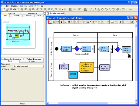
1-8 绘制活动图
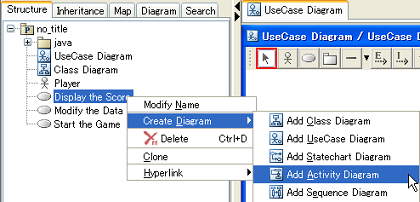
现在让我们关注 “Display the Score” 用例,并在 Activity 图上绘制它的流程。首先,您必须将 Activity diagram 添加到您的项目文件中。选择 “Displaya the Score” 的 UseCase,然后在其弹出菜单中选择 [Create Diagram] - [Add Activity Diagram]。将添加新的活动图,并在 Diagram Editor 中打开。
将活动图命名为 “Behavior of display Scores”,就像您更改 UseCase 图的名称一样。
Activity diagarm 的 Tool bar 中具有以下按钮。

现在让我们画一个活动图,如下图所示。
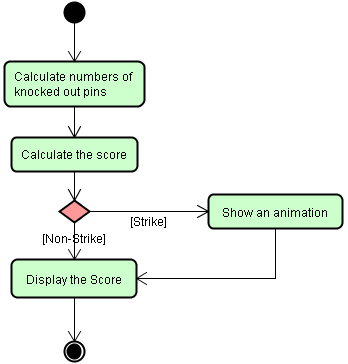
活动图与 FlowChart 图非常相似,它们描述了事物如何流动并连接到下一个作。
在此 Activity 图中,它描述了玩家投球后的事情如何进行和作,以及之后分数如何显示。从此活动图中,您可以获取当有人发出警示时将显示动画的信息。
让我们开始创建除箭头之外的所有元素。您可以按照创建 Actor 和 UseCase 的相同方式创建它们。只需从工具调色板中选择要添加的元素,然后将它们拖放到图表编辑器上即可。您可以编辑 EntryAction,该作是要在关系图编辑器或属性视图的 ActionState 中设置的作。
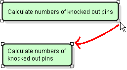
调整
“计算敲除的引脚数”的文本相当长,无法将其全部放在 ActionState 内的一行中。因此,让我们更改此 ActionState 的大小,并让此名称行分解。要更改元素的大小,请选择元素的一个角并拖动它。
现在,让我们在元素之间添加箭头以显示这些 action 对象的流程。此箭头称为 Transition。要绘制 Transition,您必须单击两个目标进行连接,就像在 UseCase 图中绘制 Association 线一样,但您必须小心,因为箭头是按您单击的顺序创建的。我将向您展示如何连续创建 Transition。
提示:如何连续创建项
- 方法 1 : 打开工具调色板上的 [所选模式]。(右起第二个按钮。
- 方法 2 : 创建元素时按住 [Shift] 键
那么到目前为止你做得怎么样?是否可以连续创建项?
当你习惯它时,它是非常有用和容易的。
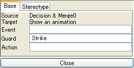
[Strike] 是 Transition 的守卫。因此,单击 Transition 箭头,然后在 Property View 的 Guard 列中输入 “Strike”。
我将介绍如何制作干净图表的三个技巧。
|
提示:多选
有三种方法可以在 Diagram Editor 上选择多个项目。
- 方法 1 :在元素上拖动并制作一个矩形。矩形中包含的所有元素都将被选中。
- 方法 2 : 从图表的弹出菜单中选择 [全选]。
- 方法 3 : 在选择多个项目时按住 [Shif] 键。
|
提示:对齐
元素可以在 JUDE 中水平和垂直对齐。让我们对左侧的项目使用 [Align vertical center](除“Show an animation”之外的所有项目)。它会使图表看起来整洁。绘制一个矩形,其中包含其内的所有左目标项以选择它们。然后从主菜单中选择 [对齐] - [垂直对齐] - [垂直对齐] ,或者您可以通过选择主菜单下方工具栏上的图标来完成此作。
|
>
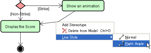
提示:线条样式
JUDE 中有两种类型的线路
| Normal Line Style (正常线型) (默认): |
用直线或多边形线连接图表元素 |
| 直角线型: |
用直角线连接图表元素 |
线条样式的默认设置为 [Normal Line Stile]。但是,[直角线型] 有时看起来不错。那么,我们为什么不为这个活动图使用 [Right Angle Line Style] 呢。选择所有线条,然后在其弹出菜单中选择 [线条样式] - [正常],或选择工具栏上的图标。
|
1-9 绘制班级图
现在我们要绘制一个类图。类图和序列图是 UML 中经常使用的图,因此我们在这里将花费比我们绘制的其他图更多的时间。
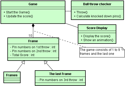
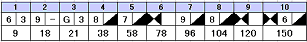
这个类图是一个专注于保龄球游戏及其分数的分析图。此类图描述保龄球游戏由十帧序列组成,每帧包含两次投掷,但最后一帧包含三次投掷。首先,将默认类图的名称更改为“分析类图”。
类图的工具 palatte 中有以下按钮。

好吧,让我们先开始绘制轮廓,然后再做细节。创建 6 个类。您可以像创建 Actor 和 UseCase 一样创建它们。
来自底部两个类的箭头称为 “Generalization”。创建 Generalizations 时,请先单击 start target。
上面类图中我们要绘制的图形中,除了 Generations 和虚线之外的所有关系都称为 Associations,您已经在 UseCase 图中绘制了它们。现在让我们画出这些 Association 线。“Game” 类和 “Frame” 类之间的关联类型称为 “合成”。通过此合成关联,这意味着游戏由帧组成,如果没有帧,则不会有游戏。
如何设置 Association 的属性
Association 有几个属性需要设置,例如 Aggregation、Composition、Multiplicity..等。在这种情况下,您需要将 Composition 设置为 Game 类。
- 方法 1 : 使用工具面板上的关联下拉列表
- 方法 2 : 在协会的弹出菜单上设置
- 方法 3 : 在关联的 Property View 上设置
此时,您为什么不从弹出菜单中使用方法 2 设置 Composition。
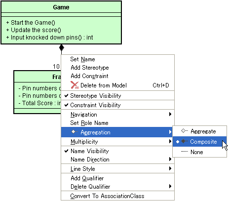
即使您选择相同的关联来打开它的弹出菜单,您也可能在弹出菜单中获得不同的菜单,具体取决于您单击它的位置。尝试单击对 Game 类关闭的关联行。然后,您可以设置 Game 类的属性。
现在,让我们从 Property View 中设置 Multiplicity。在 Diagram Editor 中选择 Association 时,Association 的属性将显示在 Property View 中(见下图),然后您可以修改 Multiplicity。
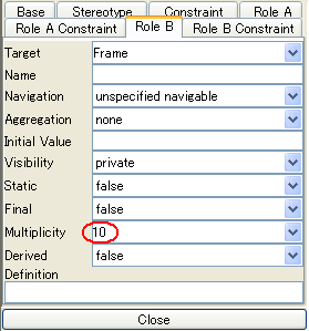
设置重数时必须小心,因为为关联的两个不同目标显示两个 role 选项卡。因此,请确保您选择了正确的一个。在这种情况下,请选择具有 Traget 的 “Frame” 选项卡,然后将多重性设置为 10。
现在,我们将向类中添加 Attributes 和 Operations。
向类添加属性
现在,我们将向 “Frame” 类添加三个 Attribute。有三种方法可以做到这一点。
- 方法 1 : 使用图表编辑器上的弹出菜单
- 方法 2 :使用项目视图中的弹出菜单。
- 方法 3 : 使用类的属性视图
在图表编辑器上选择 “Frame” 类,然后在其弹出菜单中选择 [Add Attribute]。然后键入 “Pin numbers on 1st throw” 作为属性名称。然后添加更多其他属性。您应该尝试使用上面显示的其他两种方法添加它们以进行练习。如果要删除属性,可以从 Property View 或 Structure Tree 中删除它们。Visibility (可见性) 的默认值为 private,Type (类型) 的默认值设置为 void。要更改这些默认设置,请使用 Property View (属性视图)。也可以使用快捷键 “Ctrl + F” 添加属性。(添加作的快捷键是 Ctrl + M)。
向类添加作
您可以向类添加和编辑 Operations,就像对 Attributes 执行的作完全相同。为什么不从 Property View 向类添加 Operations。
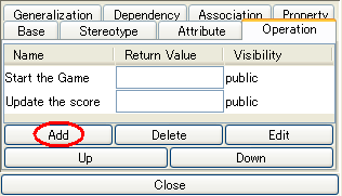
要在 Property View 上添加作,请按 [Add] 按钮。要编辑添加的作信息,请使用此属性视图或选择添加的作后,按 [编辑] 按钮,即可查看更详细的属性。您可以在此 Operation Property 对话框中编辑所有详细信息,例如 Parameters。如果要删除所选作,请按 [删除] 按钮。[Edit] 按钮用于打开作属性对话框。[向上] 和 [向下] 按钮将重新排列作顺序。好了,在你完成 “Calculate knocked down pins” 的作后,使用 Operation 属性添加一个参数 “Pin numbers : int”。
到目前为止,您做得怎么样?这一切的主要目的是使用 JUDE 绘制 UML 图,所以不用担心技术细节,继续前进。
1-10 绘制序列图
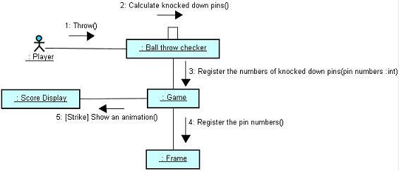
现在我们要绘制一个 Sequence 图,它显示 Game 类包含的 “Calculate knocked down pin numbers” 对象的时间序列。序列图可以添加到 Structure Tree 中的 UseCase 或 Operations 下。选择“计算敲低引脚数”的作,然后在其弹出菜单中选择 [添加序列图]。
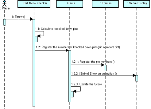
此图描述了参与交互的每个动作的时间序列,当“Player”投球时,“Ball Throw Checker”对象识别它,然后将击倒的球瓶的数量注册到“Game”对象,然后如果是击球,则“Display the Score”对象显示动画。我们绘制了一个活动图,看起来就像这样,但存在差异。在序列图中,它按时间序列显示这些内容,由垂直维度(时间)和水平维度(不同的对象)组成。
Sequence Diagram 的 Toolpalatte
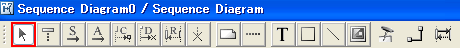
序列图中工具调色板上的这些按钮与我们在其他图表中看到的其他按钮相比看起来有点不同。因此,作元素也与我们在其他图中所做的不同。
首先,创建您在顶部看到的 5 个对象。但不要急于求成。因为我想告诉你一些事情。我们可以像往常一样,通过从 Tool 调色板中选择对象按钮来创建对象,但是在 Sequence diagram 中创建这些对象的方法非常方便。使用 Structure Tree!这就是你如何做到的。在 Structure Tree 中选择基类,然后将其拖放到 Diagram Editor 中的 Sequence 图上。
通过拖动创建对象
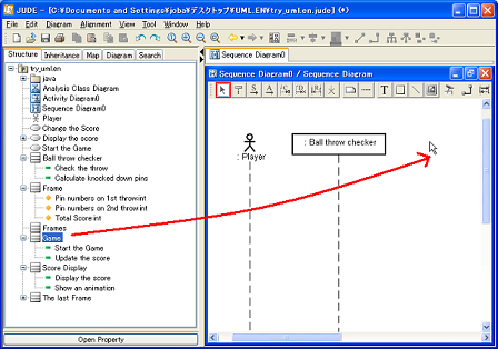
您还可以在结构树中选择多个类,然后立即将它们拖放到图表编辑器上。
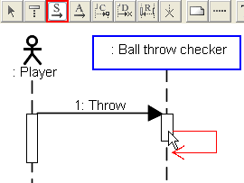
现在我们要创建消息。从 “Player” 到 “Ball Throw Checker” 对象的消息是异步消息。选择工具调色板左侧的第四个按钮。然后点击“Player”的生命线,然后点击 “Ball Checker”,消息就画出来了!现在双击名称 message0 并将其更改为 “Throw”。现在创建一条消息 “1.1 Count number of knocked down pins”,就像您刚才制作 “Throw” 消息的方式一样。完成后,让我们创建一个 Synchronous 消息,该消息从 “Ball Throw Checker” 发送出去,并将其发送给自身。(称为 SelfMessage)。选择 Tool Palette 上从左侧开始的第三个按钮。当您创建异步消息时,您单击 Lifelines。但是,在创建 Synchronous messages 时单击 Activations。
创建 Selfmessage
将作与消息关联
消息可以与作相关联。例如,当 Operation 的名称在类图中发生更改时,如果该作与消息相关,则可以自动将消息更改为相同名称。要在作和消息之间建立关系,请转到 Property 视图,同时选择 Message ,然后在 Operation 列中设置 Operation 。所以现在在 “Calculate number of knocked out pins” 消息和您刚刚创建的作之间建立关系。
在 Operation 和 Message 之间创建关系
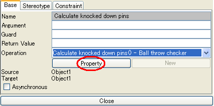
如果某些作已经与消息发送方的基类 “Ball Throw Checker” 类相关,则这些作将显示在 Operation 列中。如果尚未有与任何消息相关的作,则可以通过在属性视图中按 [New] 来添加目标作。按 [Property] 按钮将显示所选作的属性,因此您可以更改其参数名称。您不必总是有与消息相关的作,但是只需牢记在心,如果您在作和消息之间建立了关系,则可以更轻松地保持与其他图表的合规性。
现在,创建其他消息。
提示:激活大小
您可能已经注意到,每次添加新消息或移动新消息时,激活的大小都会变长。这是因为源激活需要比从 UML 规范中的源激活接收消息的目标激活函数长。因此,每次您发送新消息时,JUDE 都会自动调整它。JUDE 确实会调整激活的大小以使其增长,但不会缩短它们。如果你愿意,你可以自己缩短它们。您可以更改 Activations 的大小,方法与在 Activity 图中调整 ActionState 的大小相同。选择 激活 然后拖动角落上显示的小框以调整其大小。它适用于除 Asynchronous 消息之外的所有消息激活。
|
1-11 其他图表
以下是保龄球的协作图和 StateChart 图。
协作图
此协作图表示您在序列图上绘制的相互作。
协作工具 palatte
创建消息时单击链接。
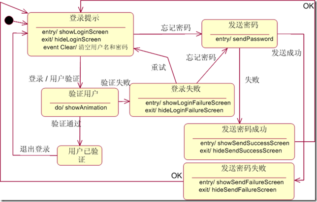
StateChart 图
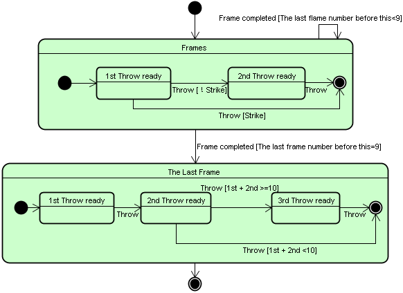
此 StateChart 图绘制了游戏如何进行的图表。
StateChart Tool palatte

1-12 JUDE 的特点
JUDE 还有更多本页未介绍的功能。请尝试以下功能。
- Java Shelton 代码导出
- 导入 Java 源文件
- Java 源文件的模板生成
- 通过在结构树中拖动来替换模型
- Boundary、Control、Entity 类的图标表示法
- 设置项目的默认颜色
- 设置构造型
的默认颜色 可以在 JUDE 系统属性中实现。
- 通过在关联线
的一角拖动来更改 Associatio 目标只需将线端拖动到其他项目,即可更改目标。
- 在 Microsoft Office 上粘贴图像 (Rasta)
- 导入 JUDE 模型
| 


 订阅
订阅