| 编辑推荐: |
本文主要介绍UML 2的类图,希望对您有所帮助。
本文来源于:agilemodeling.com,由火龙果软件Linda编辑,推荐。 |
|
UML 2 class diagrams are the mainstay of object-oriented analysis and design. UML 2 class diagrams show the classes of the system, their interrelationships (including inheritance, aggregation, and association), and the operations and attributes of the classes. Class diagrams are used for a wide variety of purposes, including both conceptual/domain modeling and detailed design modeling. Although I prefer to create class diagrams on whiteboards because simple tools are more inclusive most of the diagrams that I抣l show in this article are drawn using a software-based drawing tool so you may see the exact notation.
In this article I discuss:
Figure 1 depicts a start at a simple UML class diagram for the conceptual model for a university. Classes are depicted as boxes with three sections, the top one indicates the name of the class, the middle one lists the attributes of the class, and the third one lists the methods. By including both an attribute and a method box in the class I'm arguably making design decisions in my model, something I shouldn't be doing if my goal is conceptual modeling. Another approach would be to have two sections, one for the name and one listing responsibilities. This would be closer to a CRC model (so if I wanted to take this sort of approach I'd use CRC cards instead of a UML class diagram). I could also use class boxes that show just the name of the class, enabling me to focus on just the classes and their relationships. However, if that was my goal I'd be more likely to create an ORM diagram instead. In short, I prefer to follow AM's Apply the Right Artifact(s) practice and use each modeling technique for what it's best at.
Figure 1. Sketch of a conceptual class diagram.
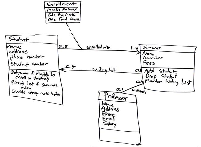
Enrollment is an associative class, also called a link class, which is used to model associations that have methods and attributes. Associative classes are typically modeled during analysis and then refactored into what I show in Figure 2 during design (Figure 2 is still a conceptual diagram, albeit one with a design flavor to it). To date, at least to my knowledge, no mainstream programming language exists that supports the notion of associations that have responsibilities. Because you can directly build your software in this manner, I have a tendency to stay away from using association classes and instead resolve them during my analysis efforts. This is not a purist way to model, but it is pragmatic because the other members on the team, including project stakeholders, don't need to learn the notation and concepts behind associative classes.
Figure 2 depicts a reworked version of Figure 1, the associative class has been resolved. I could have added an attribute in the Seminar class called Waiting List but, instead, chose to model it as an association because that is what it actually represents: that seminar objects maintain a waiting list of zero or more student objects. Attributes and associations are both properties in the UML 2.0 so they're treated as basically the same sort of thing. I also showed associations are implemented as a combination of attributes and operations – I prefer to keep my models simple and assume that the attributes and operations exist to implement the associations. Furthermore that would be a detailed design issue anyway, something that isn't appropriate on a conceptual model.
Figure 2. Initial conceptual class diagram.
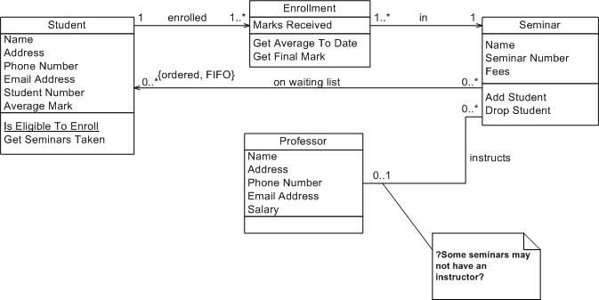
The on waiting list association is unidirectional because there isn't yet a need for collaboration in both directions. Follow the AM practice of Create Simple Content and don't over model – you don't need a bi-directional association right now so don't model it. The enrolled in association between the Student and Enrollment classes is also uni-directional for similar reasons. For this association it appears student objects know what enrollment records they are involved with, recording the seminars they have taken in the past, as well as the seminars in which they are currently involved. This association would be traversed to calculate their student object's average mark and to provide information about seminars taken. There is also an enrolled in association between Enrollment and Seminar to support the capability for student objects to produce a list of seminars taken. The instructs association between the Professor class and the Seminar class is bidirectional because professor objects know what seminars they instruct and seminar objects know who instruct them.
When I'm conceptual modeling my style is to name attributes and methods using the formats Attribute Name and Method Name, respectively. Following a consistent and sensible naming convention helps to make your diagrams readable, an important benefit of AM's Apply Modeling Standards practice. Also notice in Figure 2 how I haven't modeled the visibility of the attributes and methods to any great extent. Visibility is an important issue during design but, for now, it can be ignored. Also notice I haven't defined the full method signatures for the classes. This is another task I typically leave to design.
I was able to determine with certainty, based on this information, the multiplicities for all but one association and for that one I marked it with a note so I know to discuss it further with my stakeholders. Notice my use of question marks in the note. My style is to mark unknown information on my diagrams this way to remind myself that I need to look into it.
In Figure 2 I modeled a UML constraint, in this case {ordered FIFO} on the association between Seminar and Student. The basic idea is that students are put on the waiting list on a first-come, first-served/out (FIFO) basis. In other words, the students are put on the waiting list in order. UML constraints are used to model complex and/or important information accurately in your UML diagrams. UML constraints are modeled using the format “{constraint description}” format, where the constraint description may be in any format, including predicate calculus. My preference is to use UML notes with English comments, instead of formal constraints, because they're easier to read.
Coming soon
Figure 3. A design class diagram.
3. How to Create Class Diagrams
To create and evolve a conceptual class diagram, you need to iteratively model:
To create and evolve a design class diagram, you need to iteratively model:
An object is any person, place, thing, concept, event, screen, or report applicable to your system. Objects both know things (they have attributes) and they do things (they have methods). A class is a representation of an object and, in many ways, it is simply a template from which objects are created. Classes form the main building blocks of an object-oriented application. Although thousands of students attend the university, you would only model one class, called Student, which would represent the entire collection of students.
Classes are typically modeled as rectangles with three sections: the top section for the name of the class, the middle section for the attributes of the class, and the bottom section for the methods of the class. The initial classes of your model can be identified in the same manner as they are when you are CRC modeling, as will the initial responsibilities (its attributes and methods). Attributes are the information stored about an object (or at least information temporarily maintained about an object), while methods are the things an object or class do. For example, students have student numbers, names, addresses, and phone numbers. Those are all examples of the attributes of a student. Students also enroll in courses, drop courses, and request transcripts. Those are all examples of the things a student does, which get implemented (coded) as methods. You should think of methods as the object-oriented equivalent of functions and procedures.
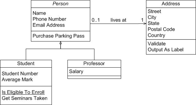
An important consideration the appropriate level of detail. Consider the Student class modeled in Figure 2 which has an attribute called Address. When you stop and think about it, addresses are complicated things. They have complex data, containing street and city information for example, and they potentially have behavior. An arguably better way to model this is depicted in Figure 4. Notice how the Address class has been modeled to include an attribute for each piece of data it comprises and two methods have been added: one to verify it is a valid address and one to output it as a label (perhaps for an envelope). By introducing the Address class, the Student class has become more cohesive. It no longer contains logic (such as validation) that is pertinent to addresses. The Address class could now be reused in other places, such as the Professor class, reducing your overall development costs. Furthermore, if the need arises to support students with several addresses¾during the school term, a student may live in a different location than his permanent mailing address, such as a dorm¾information the system may need to track. Having a separate class to implement addresses should make the addition of this behavior easier to implement.
Figure 4. Student and address (Conceptual class diagram).
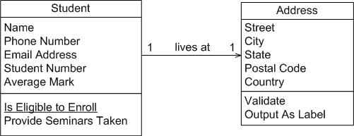
An interesting feature of the Student class is its Is Eligible to Enroll responsibility. The underline indicates that this is a class-level responsibility, not an instance-level responsibility (for example Provide Seminars Taken). A good indication that a responsibility belongs at the class level is one that makes sense that it belongs to the class but that doesn't apply to an individual object of that class. In this case this operation implements BR129 Determine Eligibility to Enroll called out in the Enroll in Seminar system use case.
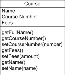
The Seminar class of Figure 2 is refactored into the classes depicted in Figure 5. Refactoring such as this is called class normalization (Ambler 2004), a process in which you refactor the behavior of classes to increase their cohesion and/or to reduce the coupling between classes. A seminar is an offering of a course, for example, there could be five seminar offerings of the course "CSC 148 Introduction to Computer Science." The attributes name and fees where moved to the Course class and courseNumber was introduced. The getFullName() method concatenates the course number, "CSC 148" and the course name "Introduction to Computer Science" to give the full name of the course. This is called a getter method, an operation that returns a data value pertinent to an object. Although getter methods, and the corresponding setter methods, need to be developed for a class they are typically assumed to exist and are therefore not modeled (particularly on conceptual class diagrams) to not clutter your models.
Figure 5. Seminar normalized (Conceptual class diagram).
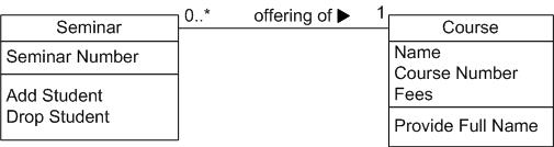
Figure 6 depicts Course from Figure 5 as it would appear with its getter and setter methods modeled. Getters and setters are details that are not appropriate for conceptual models and in my experience aren't even appropriate for detailed design diagrams – instead I would set a coding guideline that all properties will have getter and setter methods and leave it at that. Some people do choose to model getters and setters but I consider them visual noise that clutter your diagrams without adding value.
Figure 6. Course with accessor methods (Inching towards a design class diagram).
Objects are often associated with, or related to, other objects. For example, as you see in Figure 2 several associations exist: Students are ON WAITING LIST for seminars, professors INSTRUCT seminars, seminars are an OFFERING OF courses, a professor LIVES AT an address, and so on. Associations are modeled as lines connecting the two classes whose instances (objects) are involved in the relationship.
When you model associations in UML class diagrams, you show them as a thin line connecting two classes, as you see in Figure 6. Associations can become quite complex; consequently, you can depict some things about them on your diagrams. The label, which is optional, although highly recommended, is typically one or two words describing the association. For example, professors instruct seminars.
Figure 6. Notation for associations.

It is not enough simply to know professors instruct seminars. How many seminars do professors instruct? None, one, or several? Furthermore, associations are often two-way streets: not only do professors instruct seminars, but also seminars are instructed by professors. This leads to questions like: how many professors can instruct any given seminar and is it possible to have a seminar with no one instructing it? The implication is you also need to identify the multiplicity of an association. The multiplicity of the association is labeled on either end of the line, one multiplicity indicator for each direction (Table 1 summarizes the potential multiplicity indicators you can use).
Table 1. Multiplicity Indicators.
|
Indicator |
Meaning |
|
0..1 |
Zero or one |
|
1 |
One only |
|
0..* |
Zero or more |
|
1..* |
One or more |
|
n |
Only n (where n > 1) |
|
0..n |
Zero to n (where n > 1) |
|
1..n |
One to n (where n > 1) |
Another option for associations is to indicate the direction in which the label should be read. This is depicted using a filled triangle, called a direction indicator, an example of which is shown on the offering of association between the Seminar and Course classes of Figure 5. This symbol indicates the association should be read “a seminar is an offering of a course,” instead of “a course is an offering of a seminar.” Direction indicators should be used whenever it isn't clear which way a label should be read. My advice, however, is if your label is not clear, then you should consider rewording it.
The arrowheads on the end of the line indicate the directionality of the association. A line with one arrowhead is uni-directional whereas a line with either zero or two arrowheads is bidirectional. Officially you should include both arrowheads for bi-directional assocations, however, common practice is to drop them (as you can see, I prefer to drop them).
At each end of the association, the role, the context an object takes within the association, may also be indicated. My style is to model the role only when the information adds value, for example, knowing the role of the Student class is enrolled student in the enrolled in association doesn't add anything to the model. I follow the AM practice Depict Models Simply and indicate roles when it isn't clear from the association label what the roles are, if there is a recursive association, or if there are several associations between two classes.
Similarities often exist between different classes. Very often two or more classes will share the same attributes and/or the same methods. Because you don't want to have to write the same code repeatedly, you want a mechanism that takes advantage of these similarities. Inheritance is that mechanism. Inheritance models “is a” and “is like” relationships, enabling you to reuse existing data and code easily. When A inherits from B, we say A is the subclass of B and B is the superclass of A. Furthermore, we say we have “pure inheritance” when A inherits all the attributes and methods of B. The UML modeling notation for inheritance is a line with a closed arrowhead pointing from the subclass to the superclass.
Many similarities occur between the Student and Professor classes of Figure 2. Not only do they have similar attributes, but they also have similar methods. To take advantage of these similarities, I created a new class called Person and had both Student and Professor inherit from it, as you see in Figure 7. This structure would be called the Person inheritance hierarchy because Person is its root class. The Person class is abstract: objects are not created directly from it, and it captures the similarities between the students and professors. Abstract classes are modeled with their names in italics, as opposed to concrete classes, classes from which objects are instantiated, whose names are in normal text. Both classes had a name, e-mail address, and phone number, so these attributes were moved into Person. The Purchase Parking Pass method is also common between the two classes, something we discovered after Figure 2 was drawn, so that was also moved into the parent class. By introducing this inheritance relationship to the model, I reduced the amount of work to be performed. Instead of implementing these responsibilities twice, they are implemented once, in the Person class, and reused by Student and Professor.
Figure 7. Inheritance hierarchy.
Sometimes an object is made up of other objects. For example, an airplane is made up of a fuselage, wings, engines, landing gear, flaps, and so on. Figure 8 presents an example using composition, modeling the fact that a building is composed of one or more rooms, and then, in turn, that a room may be composed of several subrooms (you can have recursive composition). In UML 2, aggregation would be shown with an open diamond.
Figure 8. Modeling composition.
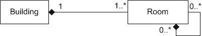
I'm a firm believer in the "part of" sentence rule -- if it makes sense to say that something is part of something else then there's a good chance that composition makes sense. For example it makes sense to say that a room is part of a building, it doesn't make sense to say that an address is part of a person. Another good indication that composition makes sense is when the lifecycle of the part is managed by the whole -- for example a plane manages the activities of an engine. When deciding whether to use composition over association, Craig Larman (2002) says it best: If in doubt, leave it out. Unfortunately many modelers will agonize over when to use composition when the reality is little difference exists among association and composition at the coding level.
In Agile Database Techniques (Ambler 2004) I discussed the importance of vocabularies when it comes to modeling XML data structures. A vocabulary defines the semantics of entity types and their responsibilities, the taxonomical relationships between entity types, and the ontological relationships between entity types. Semantics is simply a fancy word for meaning – when we're defining the semantics of something we're defining it's meaning. Taxonomies are classifications of entity types into hierarchies, an example of which is presented for persons Figure 9. Ontology goes beyond taxonomy. Where taxonomy addresses classification hierarchies ontology will represent and communicate knowledge about a topic as well as a set of relationships and properties that hold for the entities included within that topic.
Figure 9. A taxonomy for people within the university.
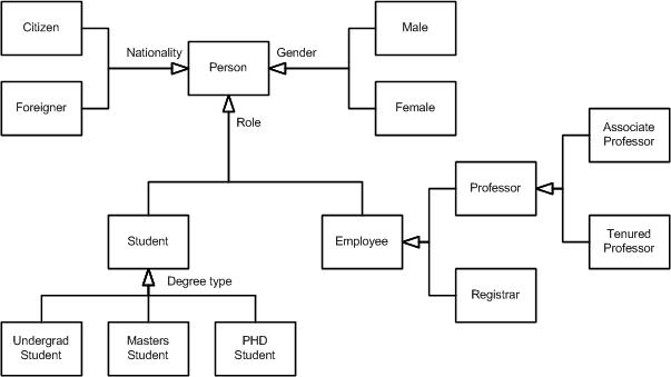
The semantics of your conceptual model are best captured in a glossary. There are several interesting aspects of Figure 9:
- It takes a “single section” approach to classes, instead of the three section approach that we've seen in previous diagrams, because we're exploring relationships between entity types but not their responsibilities.
- It uses UML 2.0's generalization set concept, basically just an inheritance arrowhead with a label representing the name of the set. In UML 1.x this label was called a discriminator. There are three generalization sets for Person: Nationality, Role, and Gender.
- These generalization sets overlap – a person can be classified via each of these roles (e.g. someone can be a male foreign student). This is called multiple classification.
- You can indicate “sub generalization” sets, for example Student within the Role generalization set.
- Some generalization sets are mutually exclusive from others, not shown in the example, where an entity type may only be in one set. This is referred to as single classification and would be modeled using an XOR (exclusive OR) constraint between the two (or more) discriminators.
This artifact description is excerpted from Chapters 8 and 12 of The Object Primer 3rd Edition: Agile Model Driven Development with UML 2.
| 


 订阅
订阅